
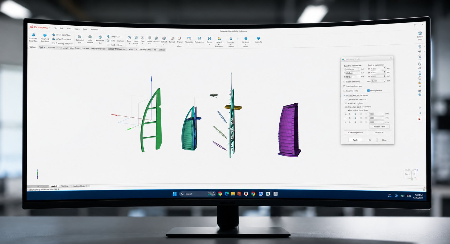
Most 3D printing delays have nothing to do with the printer. They happen before the job starts, when a file arrives in the wrong units, with a hole in the mesh, or with a wall too thin for the process. This guide covers how to prepare a file for 3D printing so it can be quoted and printed first time, whether you are sending it to a bureau like 3DWorks in Dubai or slicing it yourself.
The short answer
A print-ready file is a closed, watertight mesh (or a native CAD solid), exported in millimetres at real size, with walls thick enough for the process, saved as STEP or 3MF where you can and STL where you must, and sent with a short note on what the part is for. Do those five things and almost everything else can be sorted out at the slicing stage.
- Export from CAD as STEP, or as 3MF/STL for a finished mesh.
- Check the units and overall dimensions after export.
- Repair any open edges, flipped faces or overlapping shells.
- Confirm wall thickness, hole sizes and clearances for FDM or SLA.
- Decide the build orientation and where supports are acceptable.
- Name the file sensibly and send it with quantity, material and purpose.
Step 1: Start with the right file format
CAD solids (STEP, IGES, native SolidWorks or Fusion files) describe exact geometry with true curves. Mesh files (STL, OBJ, 3MF) describe the surface as a shell of triangles, which is what a slicer actually needs. The question is who does the conversion and how much is lost on the way.
| Format | What it carries | When to send it |
|---|---|---|
| STEP (.step / .stp) | Exact solid geometry; the slicer triangulates it on import | Engineering parts, anything that may need a dimension changed, and when a CNC quote is also wanted |
| 3MF | Mesh plus colour, materials, multiple objects and, in slicers such as PrusaSlicer, the project settings | Finished models, multi-part assemblies, and when you want to lock in orientation |
| STL (binary or ASCII) | Triangles only: no units, no colour, no material | The universal fallback for a single solid part, once the size is confirmed |
PrusaSlicer lists 3MF as its preferred format, accepts both binary and ASCII STL, triangulates STEP on import and ignores OBJ material and texture data (Prusa Knowledge Base, Supported file formats). The 3MF Consortium describes its format as a way to send “full-fidelity 3D models” between design tools, services and printers, with extensions for full colour and multi-material definitions (3MF specification). In practice: send STEP if you designed the part in CAD, 3MF if you are handing over a sliced project, and STL if that is all you have.
Step 2: Check units and scale
An STL file contains nothing but triangle coordinates. It does not say whether those numbers are millimetres or inches, so a 50 mm bracket can arrive as a 50 inch one and the slicer cannot tell the difference. Export in millimetres, then open the exported file in a viewer or slicer and read the bounding box. If the overall length is wrong, fix it at source rather than scaling in the slicer, because scaling a mesh also scales wall thickness, hole sizes and clearances.
Step 3: Make the mesh watertight
A slicer needs to know what is inside the part and what is outside. That only works if the mesh is manifold: every edge is shared by exactly two faces, every face normal points outward, and no triangles intersect. Prusa’s modelling guidance puts it simply: models must be solid or manifold, and your design software’s “make manifold” or “cap holes” tools are the way to fix errors before export (Prusa Knowledge Base, Modeling with 3D printing in mind).
Look for open edges, flipped normals, overlapping shells and stray internal geometry. Sculpting tools, photogrammetry and 3D scans are the usual sources; CAD solids exported as STEP rarely have these issues. Automatic repair in the slicer is fine for small holes; for overlapping shells, go back to the model and merge the bodies properly.
Step 4: Check walls, holes and clearances for the process
This is where FDM and SLA part ways, and where most “it looked fine on screen” failures come from. The figures below are the manufacturers’ own; treat them as floors, not targets.
FDM (filament)
An FDM wall is built from extruded lines, so its thickness has to be a sensible multiple of the line width. With a standard 0.4 mm nozzle, PrusaSlicer’s default extrusion width is 0.45 mm, giving roughly 0.9 mm for two perimeters, 1.35 mm for three and 1.8 mm for four. A wall thinner than one perimeter cannot be printed at all, and walls between one and two perimeters print badly (Prusa). Because adjacent perimeters overlap slightly, the ideal wall is a little under the simple multiple; Prusa’s worked example gives 0.86 mm for two perimeters at a 0.2 mm layer height (Prusa Knowledge Base, Layers and perimeters). For parts that will be handled or loaded, design walls at 1.2 mm or more so the slicer can use at least two full perimeters.
For mating parts, Prusa states its printers are accurate to at least 0.2 mm and recommends starting with at least 0.3 mm of clearance for movable features such as hinges, then testing. A shaft and a hole modelled at the same nominal size will bind.
SLA (resin)
Resin resolves much finer features, but thin walls can warp or detach during the peel between layers. Formlabs’ design specifications for the Form 3 and 3B, measured in Clear Resin at 100 microns, give: minimum supported and unsupported wall thickness 0.2 mm; minimum hole diameter 0.5 mm; minimum clearance 0.5 mm; minimum embossed detail 0.1 mm and engraved detail 0.15 mm; maximum unsupported overhang 5 mm at no less than 10° from level; and a minimum drain hole of 2.5 mm on hollowed parts (Formlabs design specifications). The drain hole matters: a hollow resin part with no outlet traps liquid resin and can crack.
Not sure which process suits the part? Our FDM vs SLA comparison covers the trade-offs.
Step 5: Think about overhangs and orientation before you export
A printer builds from the bed upward, so any surface that leans out over empty space is an overhang. Prusa’s guidance is that a standard 0.4 mm nozzle prints overhangs cleanly between 45° and 60° depending on settings, that short horizontal bridges print without supports, and that newer machines with 360° part cooling such as the MK4S can reach 75° (Prusa). Beyond that, the slicer adds supports, and the surface they touch will be rougher.
Three habits reduce supports without changing the part. Use chamfers rather than fillets on edges facing the bed, because a fillet creates a steep overhang where the part meets the plate. Split large or awkward parts so each piece has a flat face to print on. And orient for load: a printed part is weaker across its layer lines, so the direction it will be pulled or bent in use should decide the build orientation, not what fits the bed. If orientation matters, say so in your note or lock it in a 3MF. Finally, check the facet count on curved faces before export; CAD shading can hide faceting that will show in the print.
Step 6: What to send with the file
A file on its own produces a guess; a file with context produces a quote. When you send a model to a Dubai bureau such as 3DWorks, include the quantity (and whether more are likely later); what the part is for, since a form model, a fit check and a functional prototype are handled differently (our rapid prototyping page explains the three); any critical dimensions, marked on a screenshot or drawing; material requirements, especially heat, because a part that will live in a car cabin or on a rooftop through a Gulf summer needs a filament or resin chosen for temperature rather than the default PLA; the finish you expect; and a sensible file name (“bracket_v3_left_mm.step” says more than “final2.stl”). Zip multiple parts together.
If what you have is a sketch, a photograph with dimensions or the physical object rather than a file, that is not a problem; it goes to 3D design and modelling or scanning first, and the print file is produced from that.
Pre-flight checklist
- Exported as STEP (CAD) or 3MF/STL (mesh), in millimetres, at real size, bounding box checked.
- Mesh is watertight: no open edges, flipped normals or overlapping shells.
- Walls about 0.9 mm or more for FDM (ideally 1.2 mm+); 0.2 mm or more for SLA.
- Holes at least 0.5 mm on SLA; 0.3 mm or more clearance on FDM mating parts.
- Hollow resin parts have a drain hole of at least 2.5 mm.
- Overhangs kept under about 45° where possible; chamfers instead of fillets at the base.
- Orientation decided with strength in mind, and stated in the note.
- Quantity, purpose, material, finish and critical dimensions written down.
Frequently asked questions
What file format is best for 3D printing?
STEP if the part came from CAD, because it keeps exact geometry and can be edited or machined later. 3MF if you are handing over a mesh with colour, multiple objects or slicer settings. STL works everywhere but carries no units, so confirm the size.
Can you print from a .f3d, .sldprt or .ipt file?
Native CAD files need the original software to open. Export to STEP from Fusion, SolidWorks or Inventor instead; it is a one-click export and nothing meaningful is lost.
Does a resin part need to be hollow?
Not necessarily. Hollowing saves resin and reduces peel forces on large parts, but every hollow section then needs a drain hole of at least 2.5 mm. For small parts, printing solid is simpler and stronger.
Ready to send a file?
Run through the checklist, then send your file to 3DWorks through our contact page with the quantity, material and what the part is for. If the file needs repair or redesign, we will tell you before anything is printed.


